
Single-Switch ZVS Resonant Converters: Shrinking the Inductor for High-Density Power Design
6880_A New Family of Single-Switch ZVS Resonant Converters.
This paper introduces a new family of single-switch Zero-Voltage Switching (ZVS) resonant DC-DC converters, including Buck, Boost, and Buck-Boost topologies. The core methodology replaces the bulky filter inductor of traditional PWM converters with a high-frequency resonant LC tank, achieving high power density and soft-switching for all active elements.
TL;DR
Researchers have developed a new family of DC-DC converters that move away from the bulky inductors characteristic of Pulse Width Modulation (PWM) designs. By using a single switch and a high-frequency resonant LC tank, these topologies achieve Zero-Voltage Switching (ZVS), significantly enhancing efficiency and power density while reducing the inductor size by over 90% compared to traditional Quasi-Resonant Converters.
Background: The "Inductor Weight" Problem
In the quest for higher power density, the main bottleneck is usually the size of passive components—specifically inductors. Traditional converters like Quasi-Resonant Converters (QRC) and Soft-Transition (ZVT/ZCT) designs are essentially PWM converters with "auxiliary" resonant parts added on. They still carry a large filter inductor, limiting how small the device can actually get.
The authors solve this by moving to a pure Switched-Resonator approach, where the "filter" and "resonant" functions are merged, allowing the use of a much smaller inductor .
Methodology: The Switched-Resonator Cell
The brilliance of this paper lies in the synthesis of nine different topologies (Buck, Boost, and Buck-Boost variants) from a simple basic cell.
1. Architecture Synthesis
The converters are categorized into three connection types: G, S, and L, depending on where the resonant capacitor is tied.
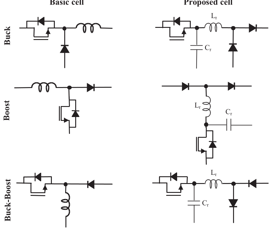 Fig 1: The basic cells used to derive the Buck, Boost, and Buck-Boost families.
2. Physical Intuition of ZVS
Instead of hard-switching, the resonance between and ensures that:
- Turn-on: The switch's antiparallel diode conducts first, clamping the voltage to zero before the gate signal is applied.
- Turn-off: The capacitor (which includes the switch's internal ) slows the voltage rise, preventing current/voltage overlap.
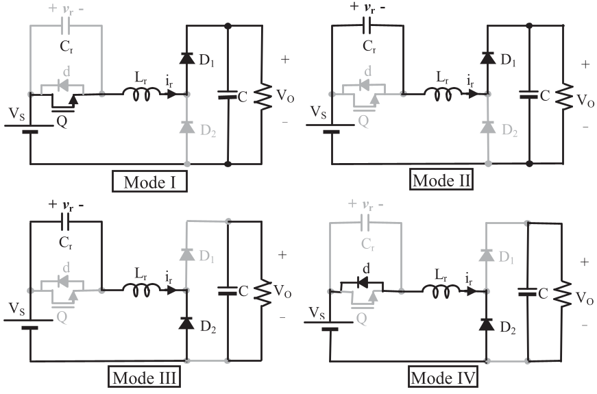 Fig 2: The proposed ZVS Buck-S converter structure.
Experimental Validation & Results
The authors validated their theory with a 100W/445kHz prototype. The experimental waveforms confirm clean ZVS transitions for the switch and soft commutation for the diodes.
- Size Reduction: The most striking result is the comparison of the inductor's magnetic energy storage. The proposed design requires an inductor volume representing only a fraction of what a standard QRC requires.
- Efficiency: The prototype maintained high efficiency across varying loads, peaking near the boundary condition.
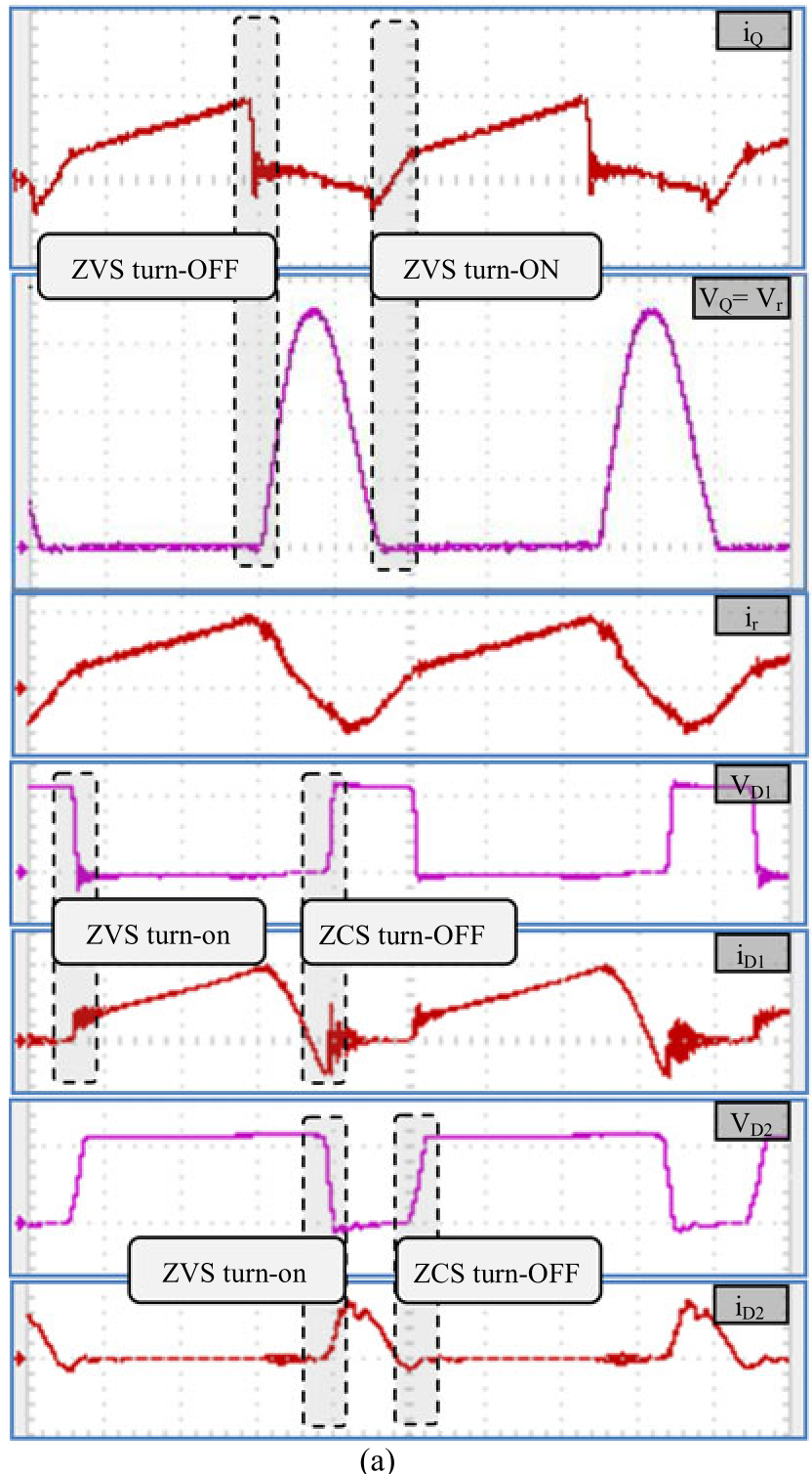 Fig 3: Experimental waveforms showing the resonant voltage and current at 100W and 130W.
Critical Analysis
Why it works:
By eliminating the heavy filter inductor and using the resonant tank for power transfer, the "circulating energy" is handled by small, high-frequency components. This is mathematically defined by the normalized load and the switch conduction angle , which the authors mapped out in detailed design charts.
Limitations:
- Voltage/Current Stress: Like most resonant converters, the peak switch voltage can be higher than the input voltage (), which requires careful device selection.
- Frequency Control: Since it is a resonant topology, frequency modulation is required for regulation, which can complicate EMI filter design compared to fixed-frequency PWM.
Conclusion
This new family of converters represents a significant step toward the "magnetics-free" (or at least "magnetics-light") future of power electronics. By combining the simplicity of a single-switch design with the sophisticated timing of ZVS, it offers a highly efficient solution for modern PD (Power Delivery) and solar energy applications.