
Electromagnetic Environmental Impact: The Hidden Cost of Power Electronics
Electromagnetic environmental impact of power electronics equipment
This paper provides a comprehensive review of the electromagnetic environmental impact caused by power electronics equipment, focusing on the generation of low-frequency line harmonics and high-frequency EMI. It categorizes noise mechanisms, evaluates international standards (IEC/IEEE), and analyzes mitigation techniques like passive/active power factor correction and EMI filtering.
TL;DR
As power electronics process nearly 60% of global electricity, "electromagnetic pollution" has moved from a niche concern to a critical infrastructure challenge. This paper by Richard Redl dissects the mechanisms of line harmonics and EMI, critiques current international standards, and presents a rigorous evaluation of mitigation strategies ranging from passive chokes to active boost rectifiers.
Problem & Motivation
The fundamental problem lies in the Commutation Process. Modern electronics don't "sip" power; they "gulp" it in distorted pulses.
- Low-Frequency Distortion: Traditional bridge rectifiers (Fig. 2) create peaky current waveforms, leading to a massive 102% Total Harmonic Distortion (THD) in worst-case scenarios. This causes distribution losses and transformer overheating.
- High-Frequency Noise: The fast switching (dV/dt and dI/dt) inherent in efficient power conversion generates conducted and radiated EMI up to 1 GHz, interfering with everything from radio reception to cellular data.
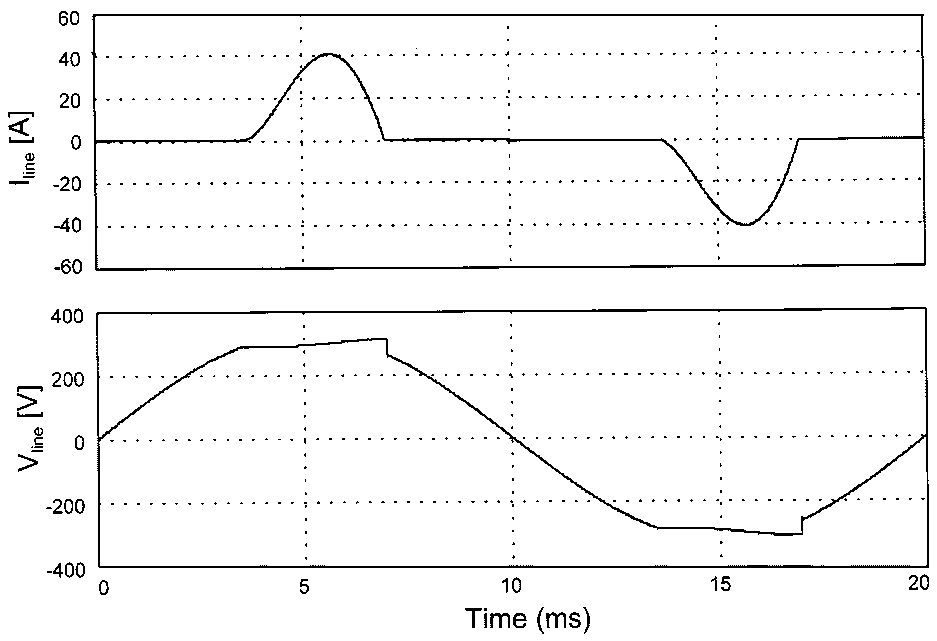 Fig 3. Real-world current (top) and voltage (bottom) distortion caused by standard capacitive rectifiers.
Methodology: Two Sides of the Interference Coin
1. Cracking the Code of Line Harmonics
The paper classifies reduction techniques into Passive and Active categories.
- Passive: Using inductors (Fig. 15) is rugged and reliable but leads to bulky, heavy designs.
- Active: The Boost Rectifier (Fig. 16a) is the "gold standard" because its input current is continuous, reducing high-frequency noise bandwidth compared to buck or buck-boost topologies.
2. High-Frequency EMI Propagation
Redl provides a crucial distinction between propagation modes:
- Differential Mode (DM): Flows between line and neutral. Result of the fundamental switching current.
- Common Mode (CM): Flows between conductors and ground. Primarily driven by parasitic capacitances (semiconductor-to-heatsink) and magnetic coupling.
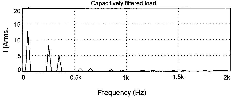 Fig 10. Parasitic paths for CM noise in a switching power supply.
Deep Insight: The "Soft-Switching" Myth
One of the most profound insights in this work is the debunking of the idea that Soft-Switching drastically reduces EMI filter size. While soft-switching (reducing dV/dt) cuts high-frequency harmonics, it rarely affects the first few harmonics (the dominant ones for compliance).
- The Result: A soft-switching converter might only gain 1 dB of attenuation headroom at 300 kHz compared to a hard-switching one. Therefore, soft-switching is an efficiency tool, not a "magic bullet" for EMC compliance.
Experiments & SOTA Comparison
The paper evaluates the IEC 61000-3-2 (Equipment-level) vs. IEEE 519 (System-level) approaches.
- Economic Impact: Complying with EN61000-3-2 increases equipment cost by 3%–5%.
- Loophole Analysis: Redl identifies "Class D loopholes" where manufacturers could technically meet standards by slightly altering waveforms while actually increasing total harmonic pollution—a critical "pitfall" for regulators.
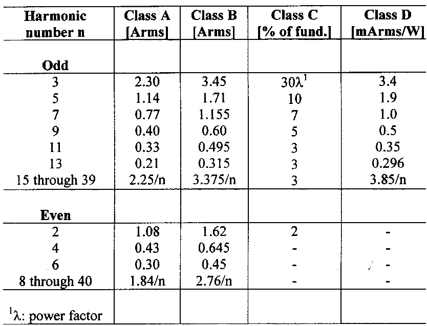 Table 1. Strict harmonic limits for different equipment classes under EN 61000-3-2.
Critical Analysis & Conclusion
Richard Redl concludes with a cautionary note for the industry. While active line-harmonic reduction cleans up the power line, it simultaneously introduces more high-frequency switching components into the environment.
Takeaway for Engineers:
- Don't over-rely on soft-switching for EMI reduction.
- Prioritize current-compensated inductors (Fig. 23) for common-mode filtering.
- Be aware that "solving" harmonics at the device level may eventually force even tighter radiated emission limits in the future due to the cumulative noise floor.
Limitations: The paper notes that measurement of high-order harmonics (up to the 40th) remains difficult and often unnecessary, as these components rarely add up constructively in the grid due to random phase distributions.