
Engineering the Drive: A Deep Dive into Gear Tooth Theory and AGMA Standards
LECTURE 7 - CHAPTERS 1213 - SPUR GEARS HELICAL, BEVEL, AND WORM GEARS
This comprehensive technical paper details the fundamental kinematic laws, geometric nomenclature, and stress analysis methodologies for various gear types, including spur, helical, bevel, and wormsets. It specifically focuses on the application of AGMA (American Gear Manufacturers Association) standards to calculate bending and surface fatigue strengths for mechanical power transmission.
TL;DR
Gears are the heart of mechanical power transmission. This paper provides a rigorous framework for designing gearsets—from simple spur gears to complex wormsets—using the Fundamental Law of Gearing and AGMA stress equations. It moves beyond basic geometry to explain how dynamic factors, material fatigue, and surface pitting dictate a machine's lifespan and efficiency.
The Core Intuition: Why Involutes?
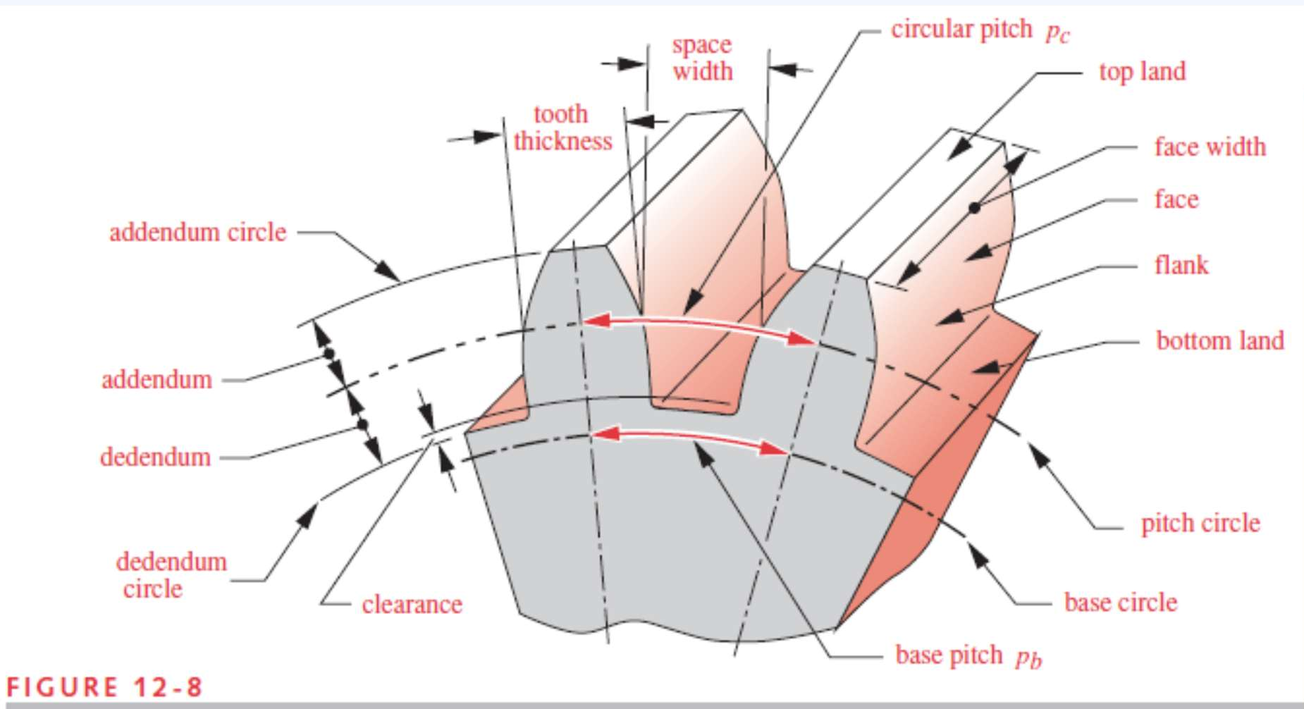
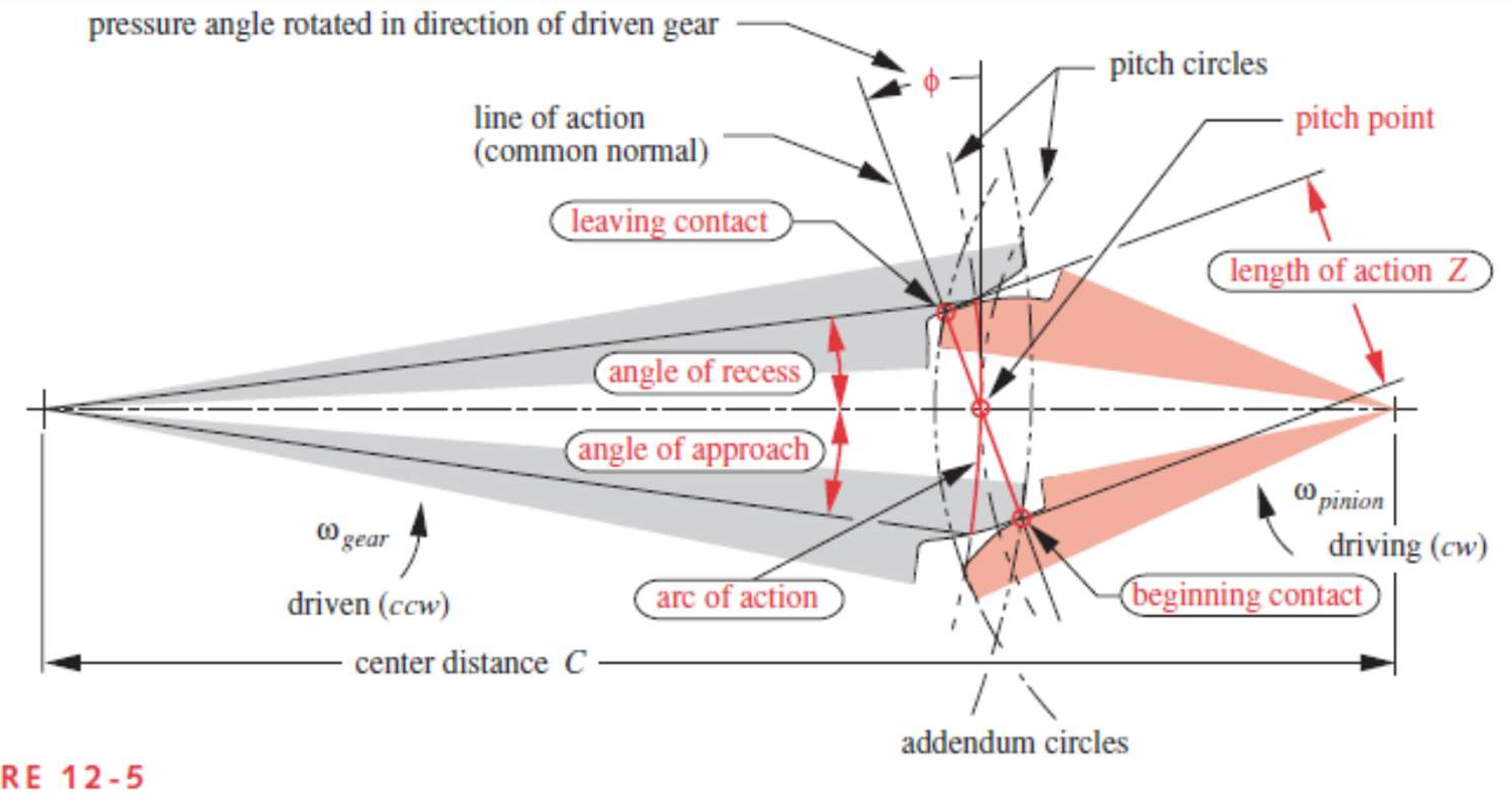
At the center of gearing is the Fundamental Law of Gearing: the angular velocity ratio must remain constant throughout the mesh. The paper explains that this is achieved when the common normal of the tooth profiles always passes through a fixed pitch point.
While several curves could satisfy this, the Involute form dominates industry. Why? Because it maintains the velocity ratio even if the center distance between shafts varies slightly—a critical practical advantage for manufacturing and assembly.
Methodology: The AGMA Factor Approach
The paper transitions from pure kinematics to structural integrity. It identifies two primary failure modes:
- Fatigue Fracture: Root bending stress exceeds material limits.
- Surface Fatigue (Pitting): Cyclic contact pressure causes surface failure.
Bending Stress (The Lewis Evolution)
The classical Lewis equation is expanded into the AGMA Bending Stress Equation:
This isn't just math; it's a "Correction Factor" philosophy.
- (Dynamic Factor): Accounts for the "shock" of teeth coming into mesh at high speeds.
- (Geometry Factor): Encapsulates the specific shape and radius of the tooth.
- (Load Distribution): Corrects for shaft misalignments that force one side of the tooth to work harder than the other.
Surface Stress (The Buckingham Influence)
Pitting is addressed via the Buckingham Equation, which considers the "Elastic Coefficient" (). This accounts for the material pairing—for example, a steel pinion running against a bronze gear behaves differently than steel-on-steel due to differences in Young's Modulus and Poisson's ratio.
Specialized Gearing: Helical, Bevel, and Wormsets
The paper provides specific insights for non-parallel shafts:
- Helical Gears: Offer smoother, quieter operation due to higher contact ratios, but introduce axial thrust () that requires specialized bearings.
- Bevel Gears: Designed on "mating cones" for intersecting shafts. The paper emphasizes the Geometry Factor J differences for straight vs. spiral bevels.
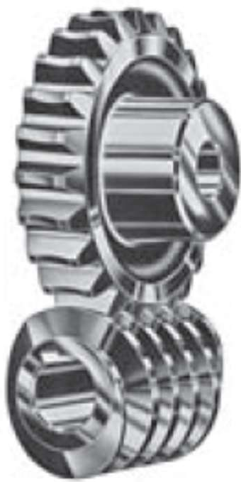
- Wormsets: The masters of high gear ratios (up to 360:1). However, the paper warns of low efficiency due to high sliding friction, necessitating a different rating method based on heat dissipation and oil film temperature.
Experimental Guidance & SOTA Standards
The tables provided (e.g., Table 12-20) are the "Standard of Truth" for engineers. They define fatigue strengths at cycles with 99% reliability.
One critical insight is the Hardness Ratio Factor (). The paper notes that if the pinion is significantly harder than the gear, it actually "work-hardens" the gear surface during the run-in period, effectively increasing the gear's strength—a fascinating example of how mechanical use can enhance component properties.
Critical Analysis & Conclusion
Takeaway
Gear design is not a "plug-and-play" formula. It requires a deep understanding of the environment (Application Factor ) and the manufacturing quality (Quality Index ).
Limitations
The paper relies heavily on AGMA standards which are primarily U.S.-centric. While it provides metric (SI) conversions, global designers must often reconcile these with ISO standards, which may vary in their calculation of the dynamic factor . Additionally, while the paper excels in analytical modeling, it notes that data for non-steel materials (like high-performance plastics or composites) is still under-developed.
Future Outlook
As EV drivetrains demand higher RPMs and lower noise profiles, the "Quality Index" and "Dynamic Factors" discussed here will become even more critical, likely moving from analytical approximations to real-time simulation and digital twin monitoring.