
Precision in High-Current Sensing: Mastering the Summing Network and Trace Compensation
4178_A Novel Approach Based on Trace Resistance Compensation for Summing Networks for High-Current Measurement.
This paper introduces a novel high-current sensing approach using a summing network with integrated PCB trace resistance compensation for paralleled shunt resistors. The method significantly reduces measurement errors caused by current and thermal imbalances, achieving a minimum error of ±0.072% at 100 A.
TL;DR
Measuring high currents (100A+) usually forces a trade-off between cost and accuracy. This paper breaks that deadlock by introducing a summing network with trace resistance compensation. By treating PCB traces not as parasitics, but as part of a mathematical averager, the authors reduced measurement errors from 4.5% to a stunning 0.072% at full load.
The "Stubborn" Reality of High-Current Shunts
In high-power electronics, we rarely use a single shunt resistor because the thermal density would be catastrophic. Instead, we parallel them. However, physics is rarely "fair"—copper traces have finite resistance, and current rarely splits perfectly among parallel branches.
The Prior Work fails here because:
- Asymmetry: Different trace lengths to the sensing amplifier create voltage offsets.
- Thermal Imbalance: External heat sources or uneven current distribution change the copper resistance (), leading to dynamic errors.
- Cost: Isolated amplifiers are accurate but expensive (~$30 USD per unit), while cheap ICs can't handle the 100A+ scale.
Methodology: The Trace as a Tool
The authors' core insight is to transform the PCB layout into a Summing Network. Instead of just picking a single point to sense, they take the voltage drop from all parallel resistors and average them through a network of resistances.
1. The Averaging Physics
By applying Millman’s Theorem, the output voltage () becomes the average of all shunt drops: This effectively "cancels out" the error if one resistor is carrying more current than its neighbors.
2. Micro-Level Trace Compensation
Rather than adding external resistors (which adds cost and tolerance error), the authors use the PCB traces themselves () as the summing resistors. They meticulously calculate the length () and width () of each sensing trace to ensure every branch has the exact same resistance value before reaching the amplifier.
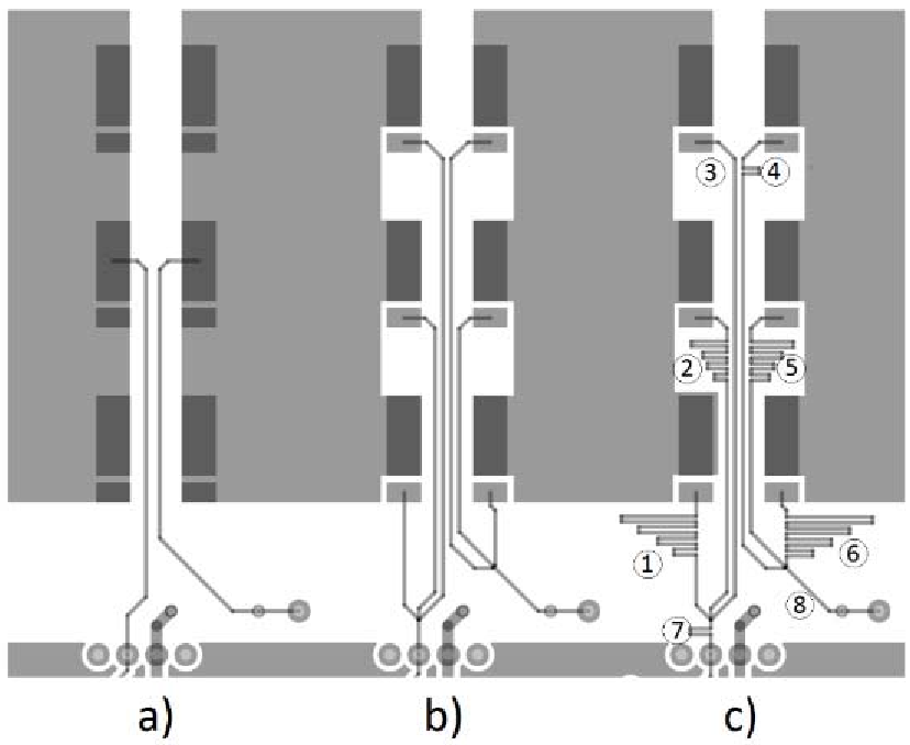 Figure 1: Comparison between No Summing (a), Simple Summing (b), and the Proposed Trace-Compensated Summing (c).
Experimental Results: Better Under Pressure
The team built a 100-A prototype and tested it against two baselines. Interestingly, the method performed even better under high temperatures.
- Baseline (No Summing): ~4.7% error.
- Proposed Method: 0.108% error with fan cooling, and a remarkable 0.072% error without cooling at 100A.
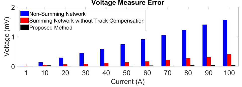 Figure 2: Thermographic analysis showing temperatures exceeding 108°C. The proposed method remains stable despite these extremes.
The data suggests that the natural rise in copper resistance due to temperature may actually help "self-correct" minor manufacturing mismatches in the trace lengths, provided the layout is balanced.
Critical Insight & Conclusion
This work highlights a fundamental principle in power electronics: The layout IS the circuit. By moving the complexity from the silicon (active ICs) to the substrate (PCB traces), we can achieve industrial-grade precision for a fraction of the cost.
Future Outlook: While this method addresses DC and low-frequency accuracy, the next frontier is applying similar "compensated averaging" to high-frequency transients in Wide-Bandgap (GaN/SiC) converters, where parasitic inductance replaces resistance as the primary enemy.
Key Takeaway: If you are designing for high-current Overcurrent Protection (OCP) or monitoring, stop looking for better amplifiers and start designing better summing traces.